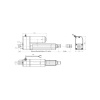
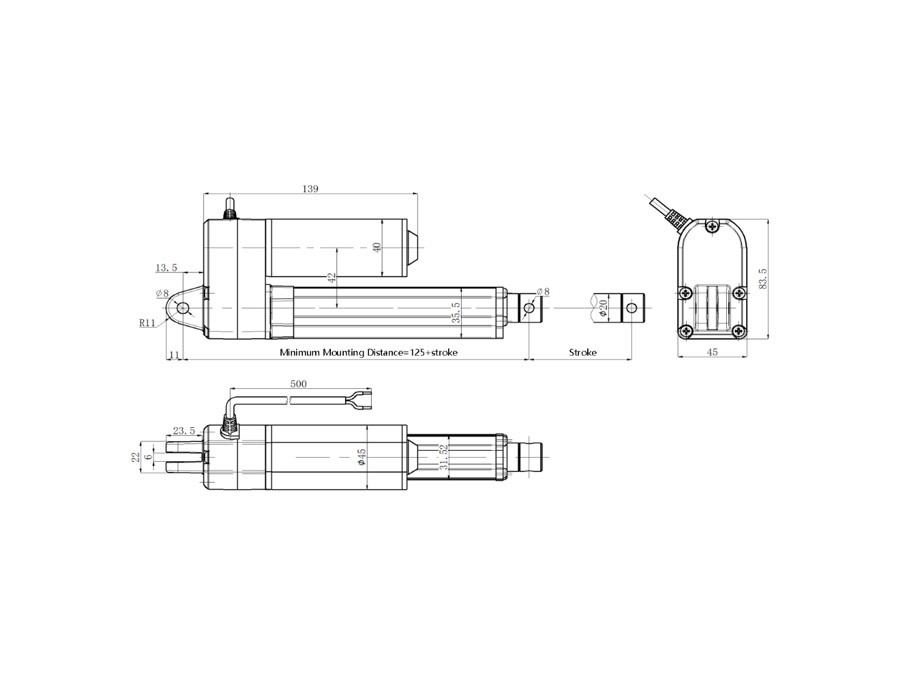
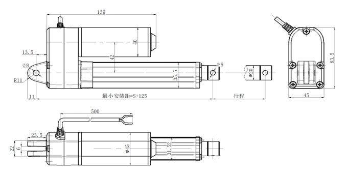
30≤S<400mm; S+125
400≤S<1000mm; S+175
1000≤S<1500mm; S+225
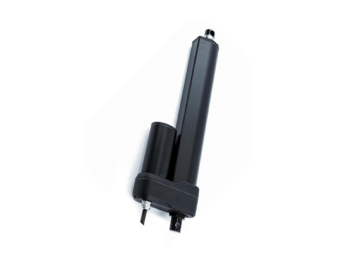
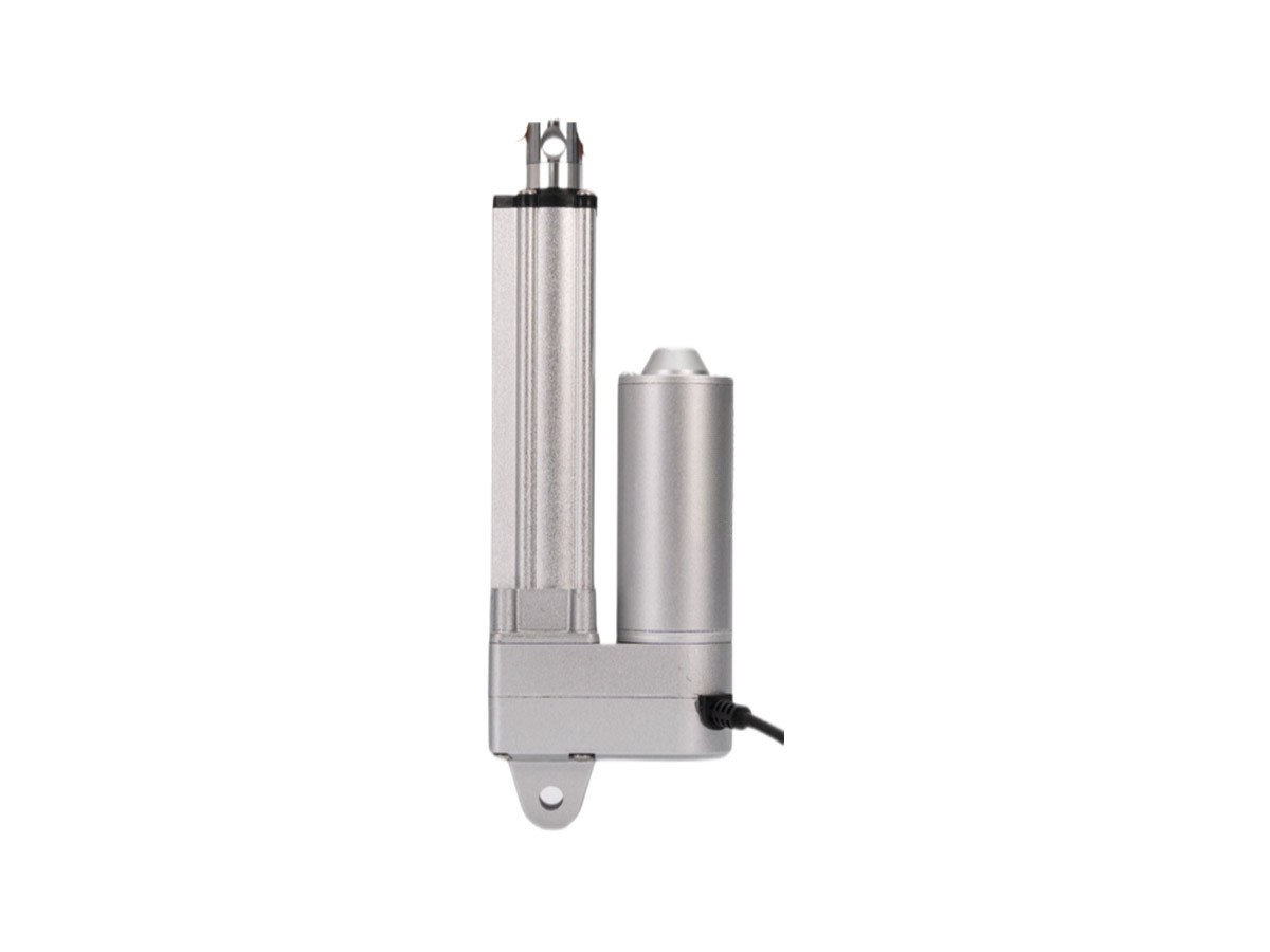
Advantages
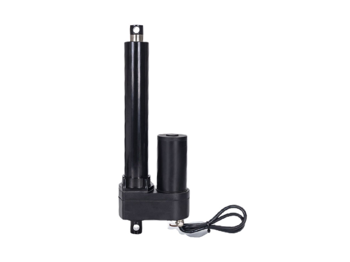
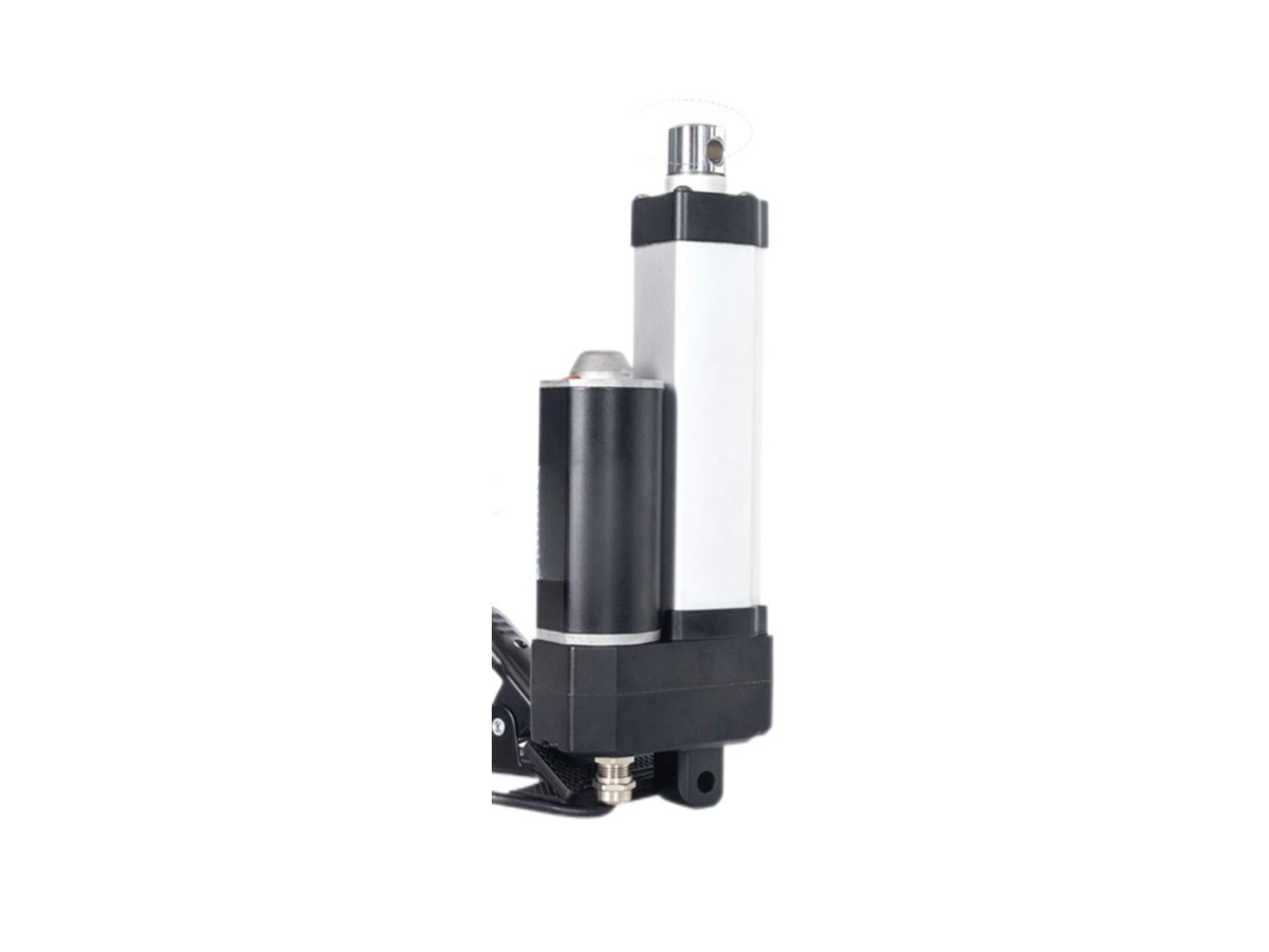
It’s made for medium loads up to 2000N. It’s super quiet, has really good protection (IP65/IP66, so it holds up well in different environments), and locks securely on its own. We often see it used in furniture, medical gear, or automation stuff where noise and protection matter. It can be adjusted to the stroke you need, works with wired or wireless controls, and lasts for 25,000 uses—pretty reliable for those specific needs!"
Common Applications
Furniture, medical equipment, automation devices, and other high-demand scenarios requiring low noise and high protection.
Ideal for precision environments where quiet operation and reliability are critical.
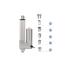
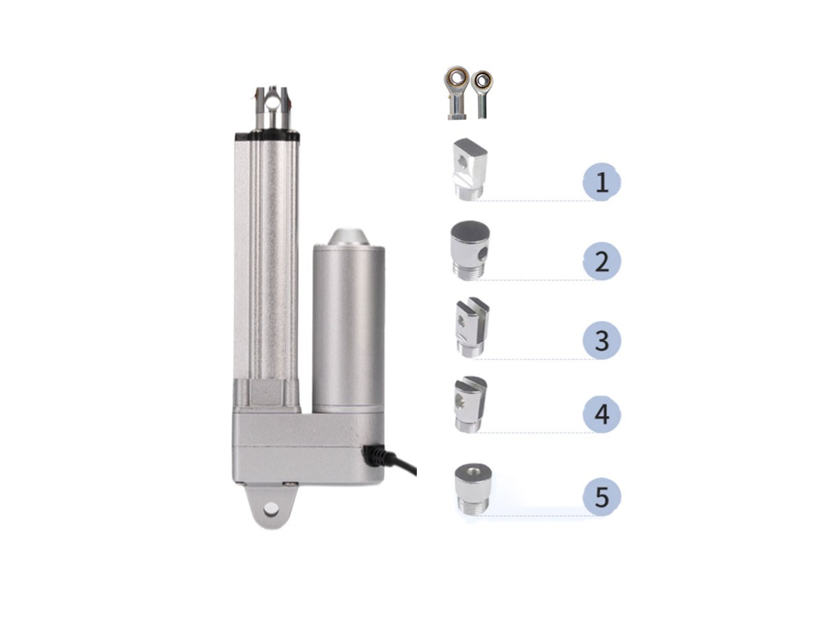
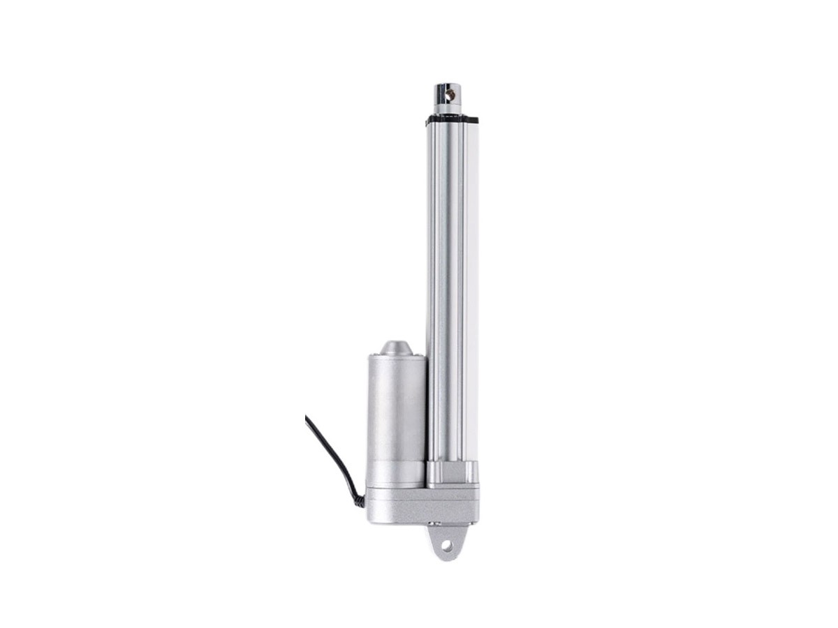
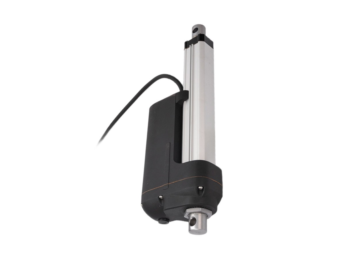
Customizable front/rear joints.
|
Code
|
No-load Speed(mm/s)
|
Load Speed(mm/s)
|
Load(N)
|
No-load Current (A)
|
Load Current (A)
|
|
12V
|
24V
|
36V
|
48V
|
12V
|
24V
|
36V
|
48V
|
|
A
|
13.0
|
7.5
|
2000
|
0.7
|
0.4
|
0.3
|
0.18
|
7
|
3.5
|
2.7
|
1.8
|
|
B
|
18.0
|
10.0
|
1800
|
|
C
|
23.0
|
12.0
|
1500
|
|
D
|
34.0
|
18.0
|
1000
|
|
E
|
55.0
|
30.0
|
800
|
Note: The data is measured at room temperature may have deviations of up to ±10%.
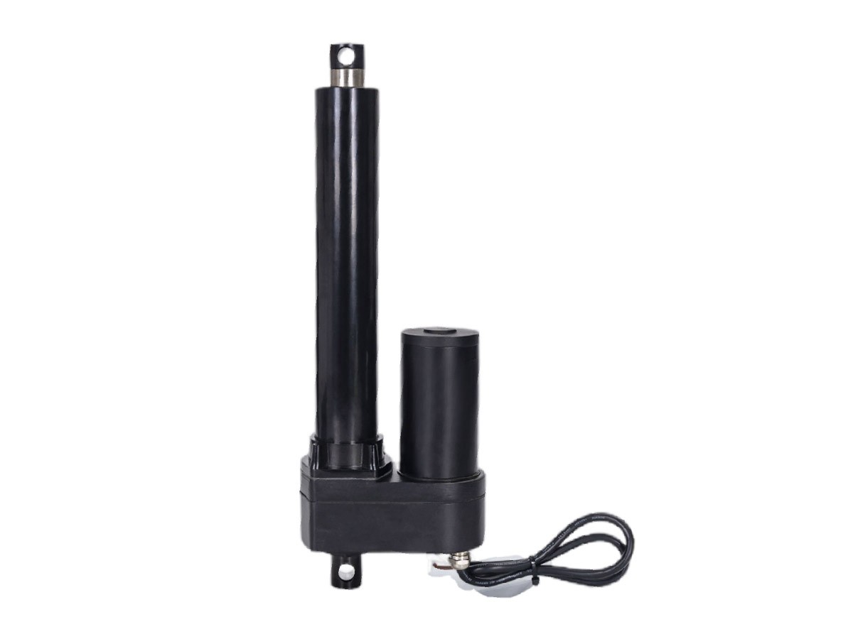
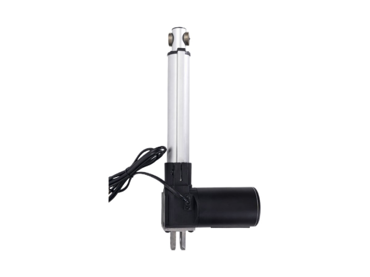
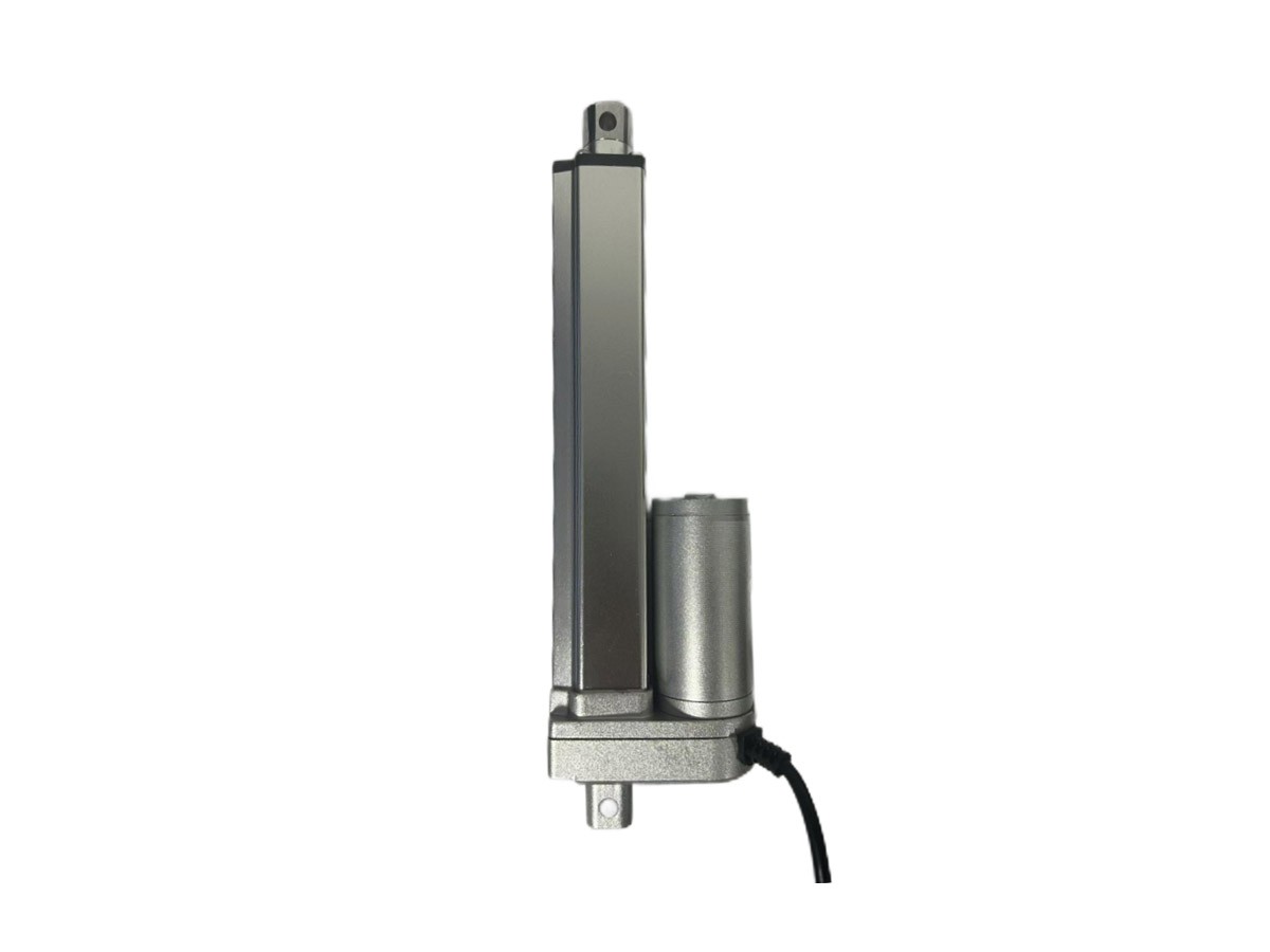
Mechanical Configuration
Front/rear joint styles available as options or customizable. Special Note: Rod-end joint bearings may affect the minimum installation distance (applies to all models).