-
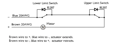
Potential-free chronometer
-

10 ≤ travel<400, minimum installation distance=travel+105
400 ≤ travel<1000, minimum installation distance=travel+150
1000 ≤ travel<1500, minimum installation distance=travel+200
-
Timing with potential
-
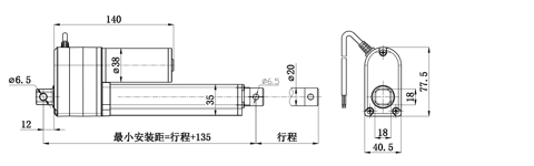
10 ≤ travel<400, minimum installation distance=travel+135
400 ≤ travel<1000, minimum installation distance=travel+185
1000 ≤ travel<1500, minimum installation distance=travel+235
Features
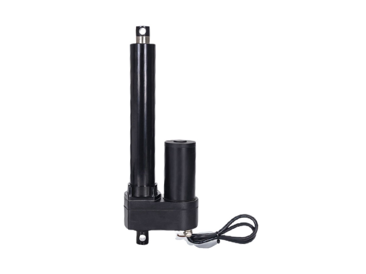
High Protection (IP65/IP66)
Metal Gears (long lifespan, impact-resistant)
Service Life: 25,000 operation cycles
Common Applications
Harsh environments (e.g., sweeper trucks, mist cannon trucks, automated equipment)
Scenarios prioritizing stability and protection over noise reduction
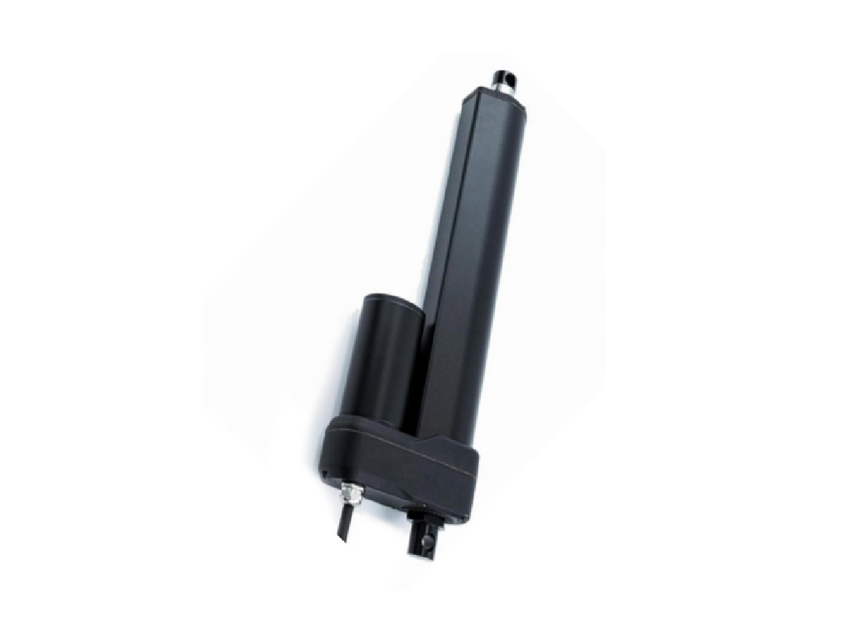
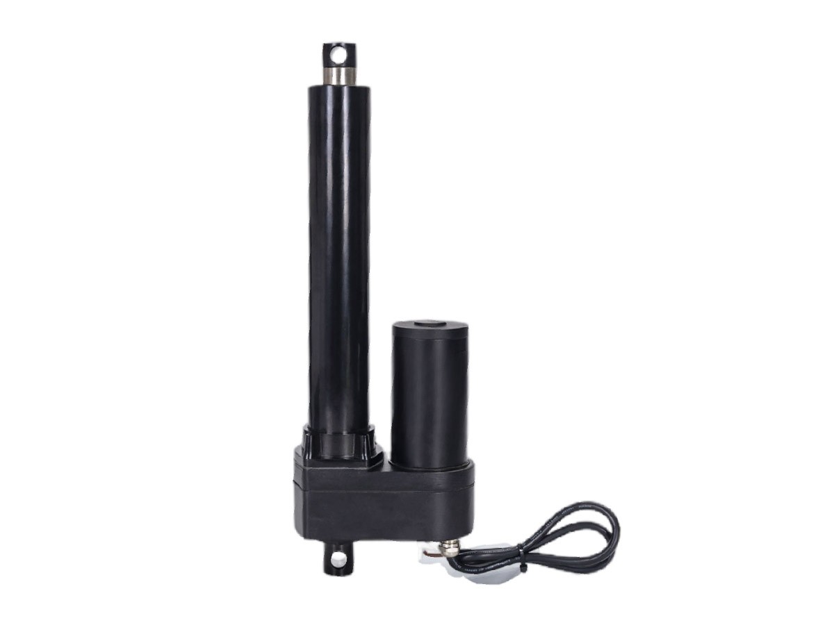
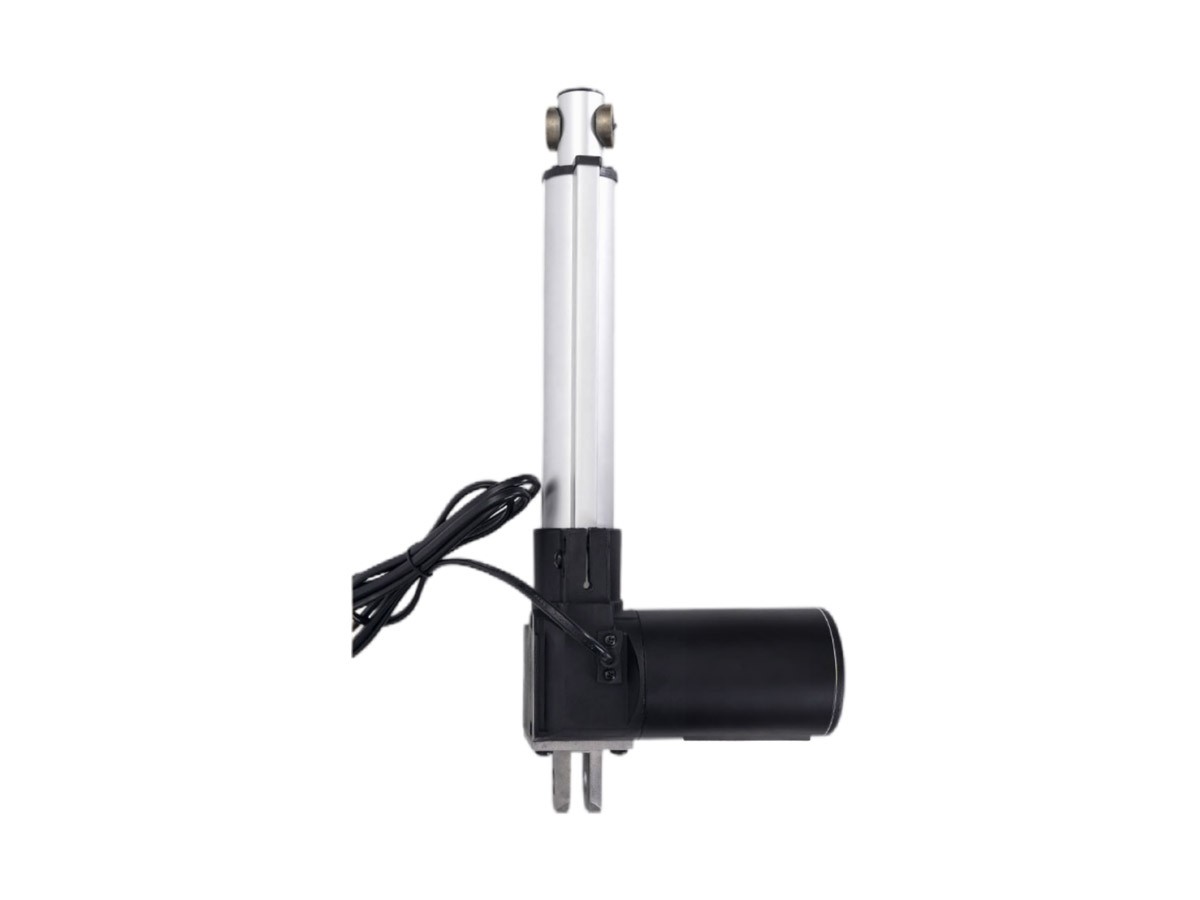
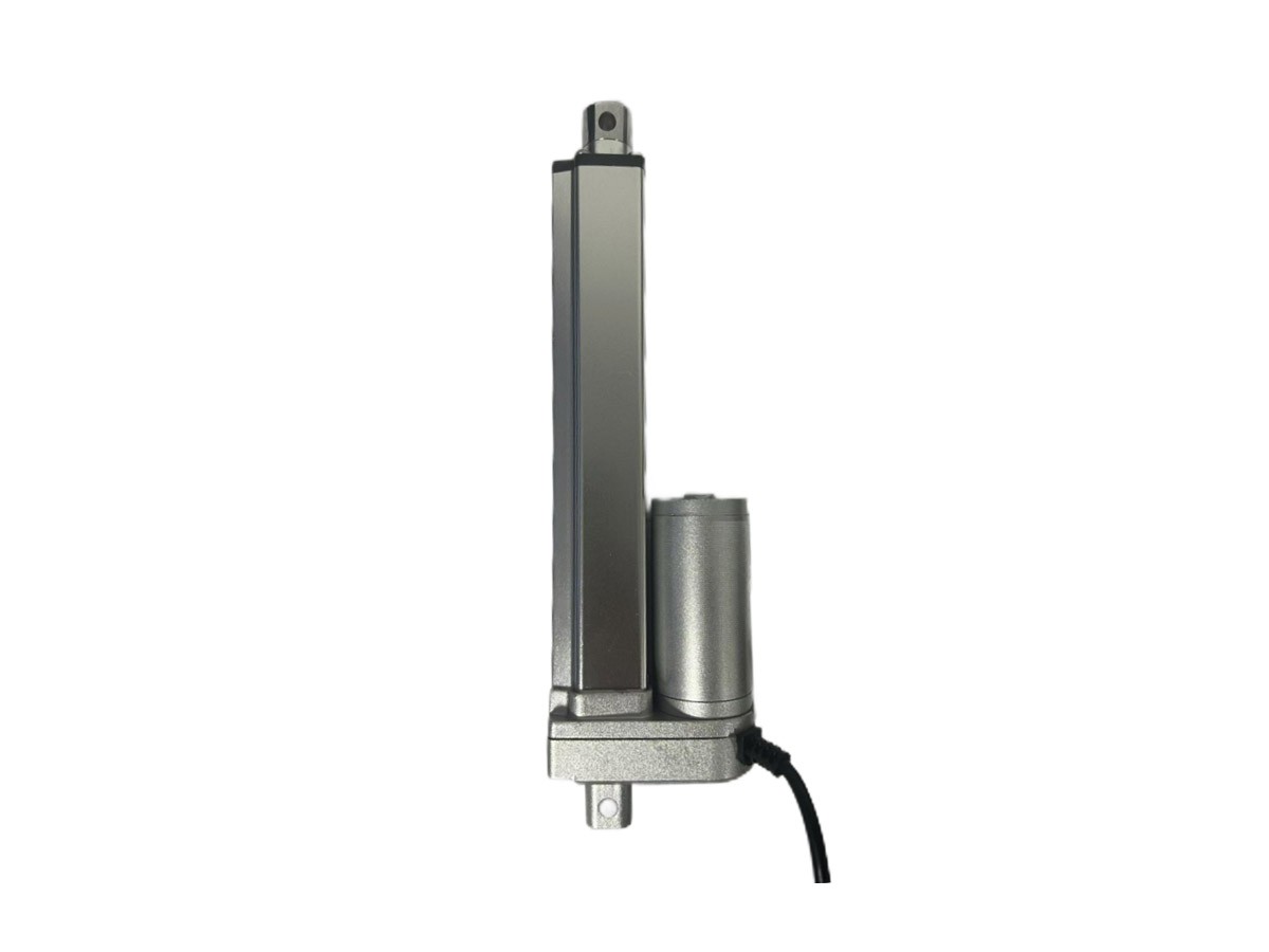
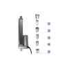
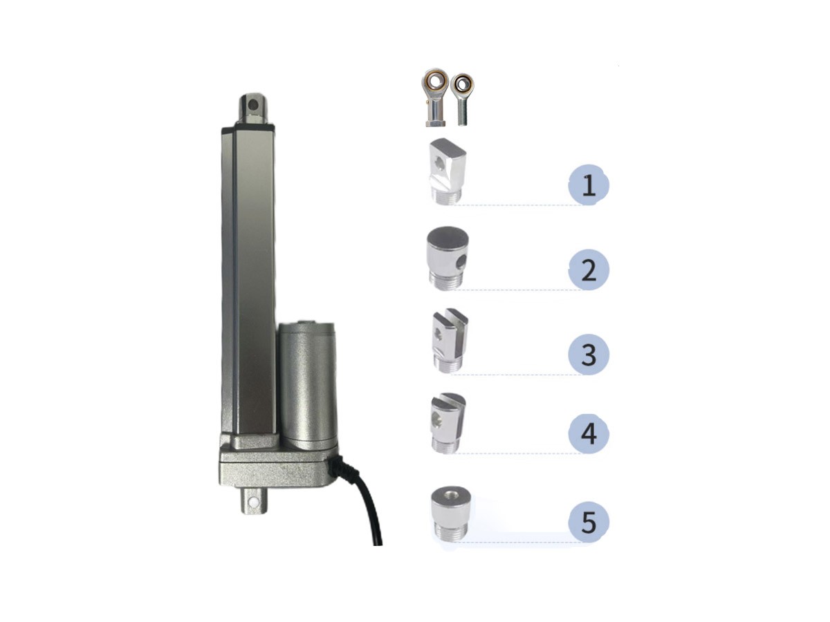
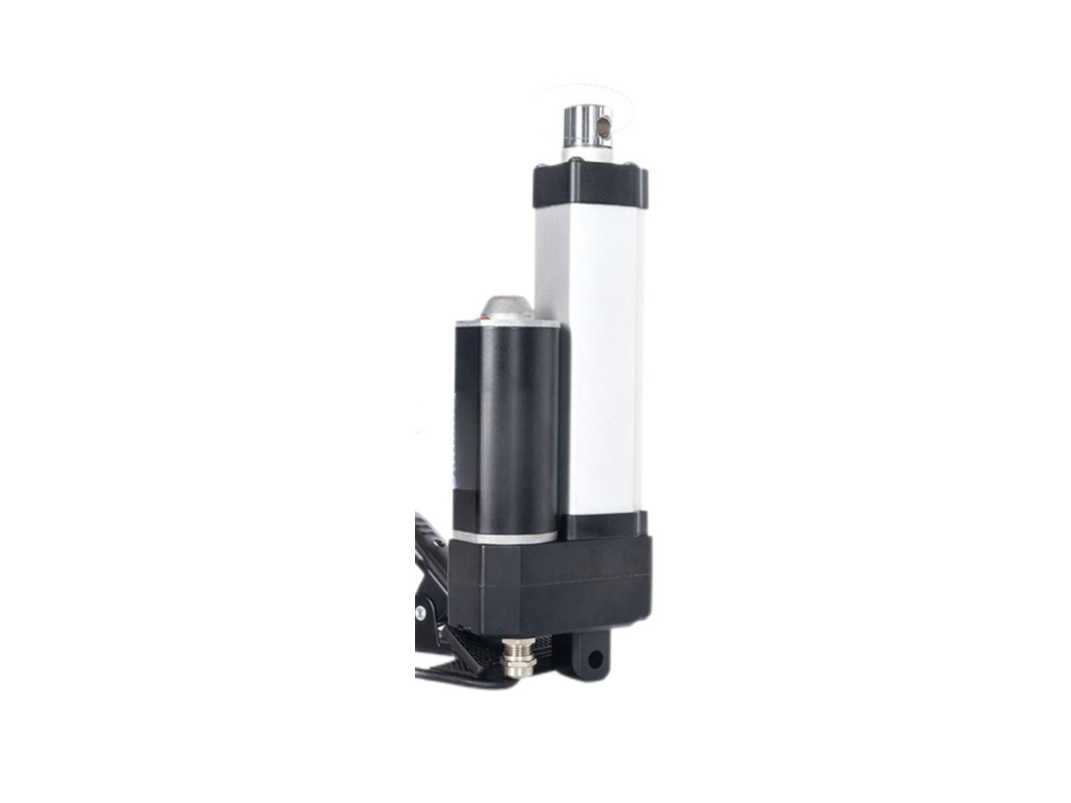
Customizable front/rear joints.
|
Voltage: 12/24/36/48V DC
|
|
Max Load: 2000N
|
|
Max Stroke: Customizable not exceeding 1000mm
|
|
Minimum Mounting Distance: Refer to the drawing
|
|
Max Speed: 5-160mm/s
|
|
Protection Level: IP65/IP66
|
|
Operating Temperature: -20°C to 60°C
|
|
Noise Level: ≤65dB
|
|
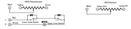
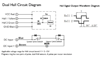
Controllers: Wired controller, wireless controller
|
|
Signal Outputs: Hall sensors, magnetic switches, limit switches
|
|
Code
|
No-load Speed mm/s
|
Load Speed mm/s
|
Max Load (N)
|
No-load Current(A)
|
Full-load Current(A)
|
|
12V
|
24V
|
36V
|
48V
|
12V
|
24V
|
36V
|
48V
|
|
A
|
5
|
3
|
2000
|
0.5
|
0.3
|
0.2
|
0.15
|
5.4
|
2.5
|
3.8
|
1.2
|
|
B
|
7
|
4
|
1800
|
|
C
|
12
|
6
|
1500
|
|
D
|
15
|
8
|
1000
|
|
E
|
20
|
10
|
800
|
|
F
|
25
|
13
|
700
|
|
G
|
38
|
19
|
500
|
|
H
|
45
|
23
|
400
|
|
I
|
55
|
28
|
300
|
|
J
|
65
|
33
|
250
|
|
K
|
100
|
50
|
200
|
|
L
|
160
|
80
|
100
|
Note: The data in the table is measured at room temperature. Due to parts processing and installation precision, there may be errors with a maximum deviation of ±10%.
☆ Explanation on Self-locking Force:
1. If the push rod is used horizontally and reaches the end in an unloaded state, there is no need to consider self-locking.
2. If the push rod is used non-horizontally or has a load when fully extended, selflocking should be considered.
3. For the second scenario, it is recommended to choose a lead not greater than 5, Otherwise, with gear and internal transmission wear, self-locking force may gradually decrease, leading to inability to self-lock.
4. Our wired controllers have a function to increase self-locking force. If not purchased together, it is recommended that customers ensure the motor wires of the push rod are short-circuited when designing the control system, which can increase selflocking force by about 20%.
Mechanical Configuration
Front/Rear Joint Styles: Available in standard options or customizable
Ball screw, copper nut, timing belt drive, manual crank function, or full IP66 protection can be selected per customer requirements.
Standard brushed motors available. Optional stepper, servo, or brushless motors (motor dimensions must not exceed 42×42mm; no height restriction). Electromagnetic brakes can be freely combined to achieve emergency stopping of the actuator.