-
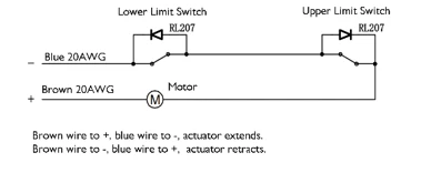
Unlimited switch, clutch mechanical limit protection
-

50 ≤ travel<599, minimum installation distance=travel+200
600 ≤ travel<1000, minimum installation distance=travel+250
1000 ≤ travel<1500, minimum installation distance=travel+300
-
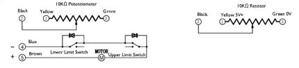
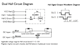
Built-in limit switch, clutch mechanical limit protection (optional potentiometer signal output)
-

50 ≤ travel<599, minimum installation distance=travel+250
600 ≤ travel<1000, minimum installation distance=travel+300
1000 ≤ travel<1500, minimum installation distance=travel+350
Advantages
High protection (IP65/IP66)
High structural strength (steel telescopic rod, copper nut)
Metal gears (long lifespan, impact resistance)
Strong self-locking force (built-in self-locking torsion spring), overcurrent protection
Disadvantages
High noise level (70db), generally recommended for outdoor use
Common Applications
Agricultural machinery, truck bucket lifting, and other applications with high load requirements and harsh operating environments
Low requirements for noise, stability, and protection level
Scenarios with demand
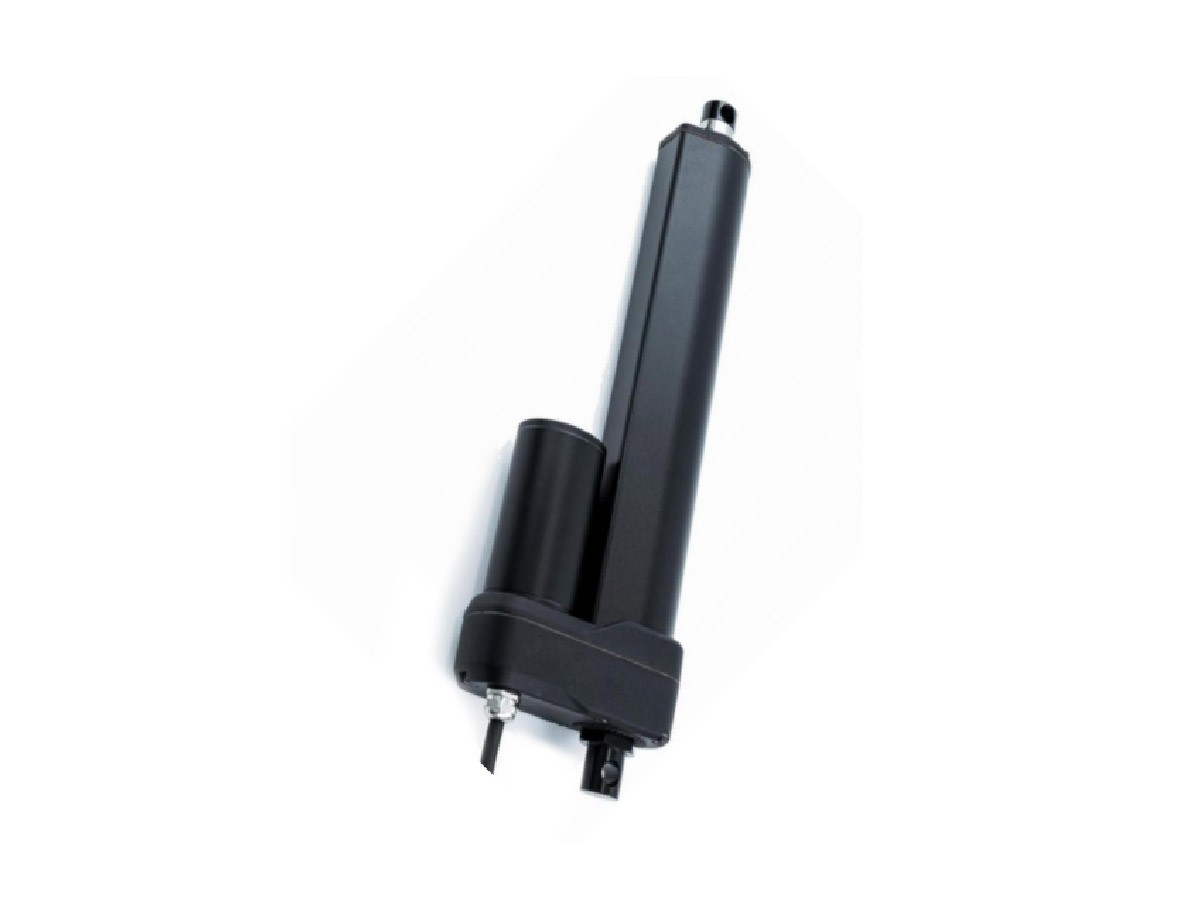
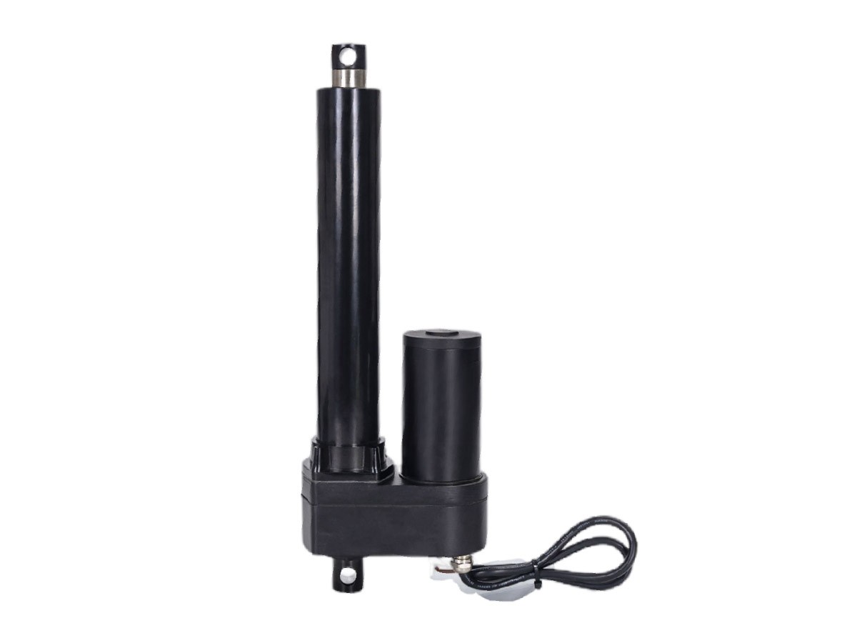
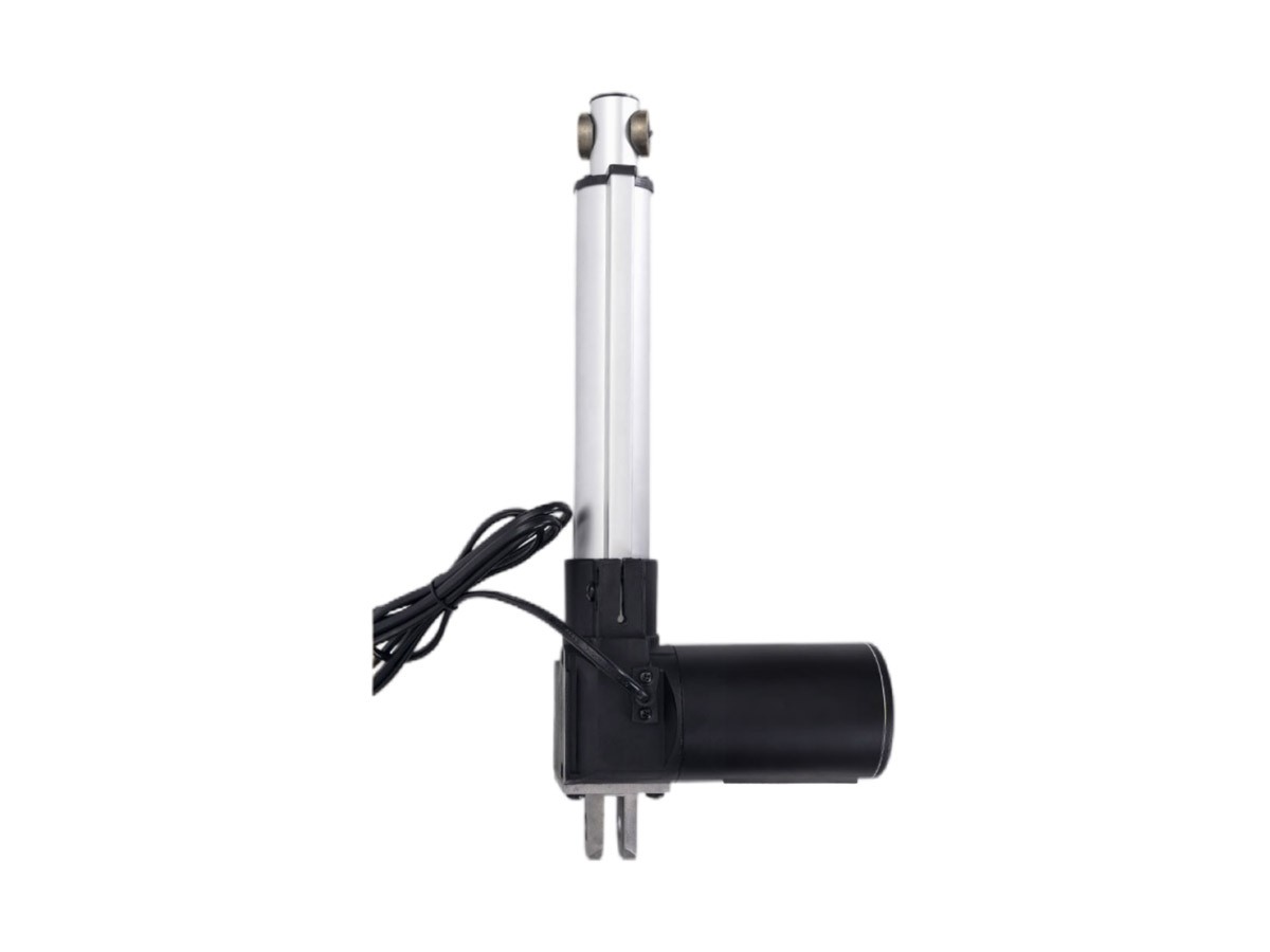
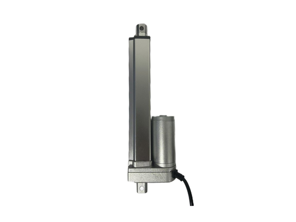
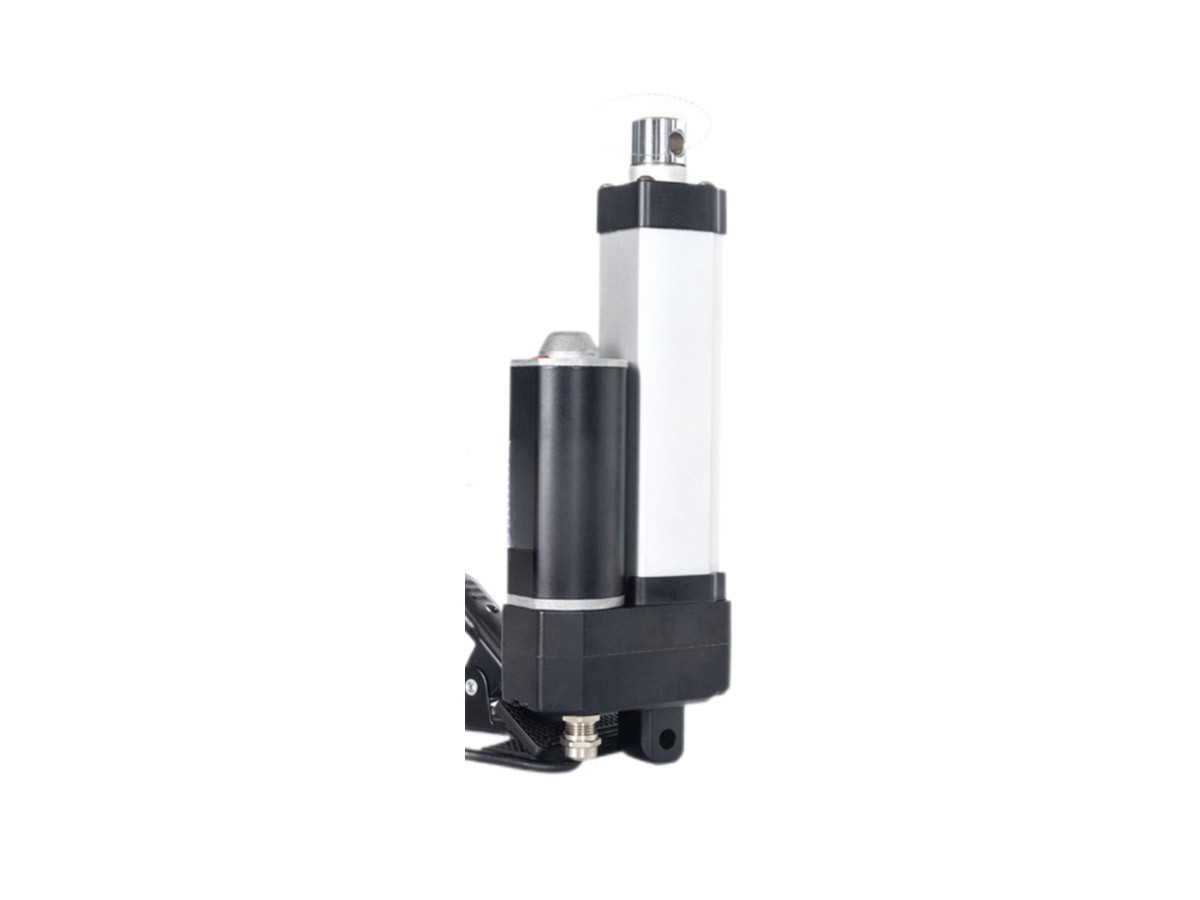
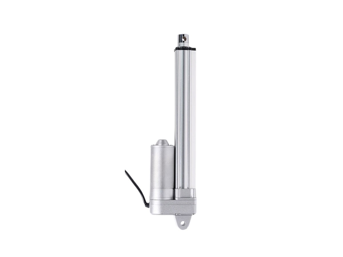
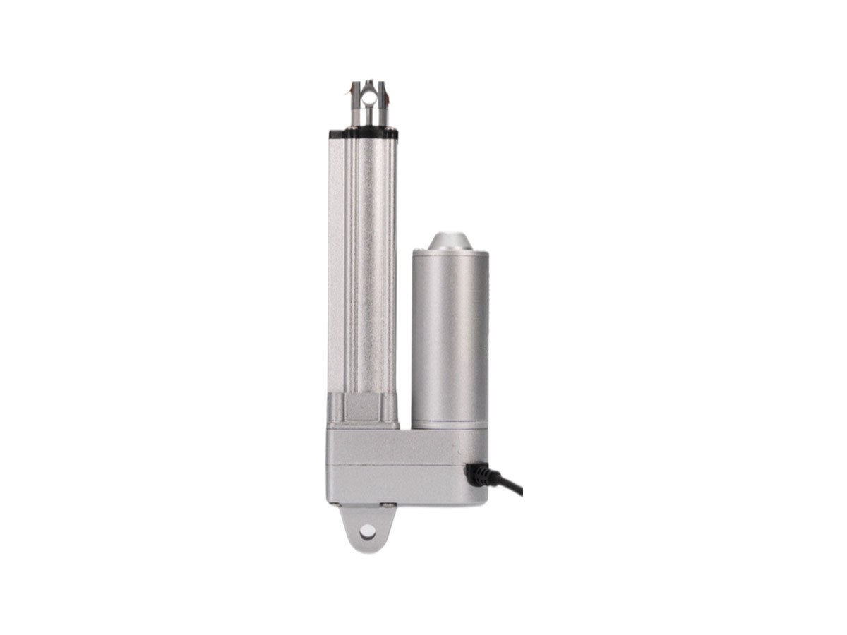
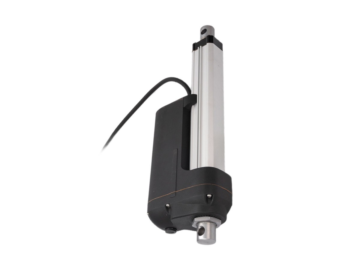
The front-end and back-end connectors can be customized
|
Code
|
Gear Ratio
|
Screw Lead
|
No-load speed(mm/s)
|
Full load speed(mm/s)
|
Ex-factory standard(N)
|
Self-locking force(N)
|
No-load Current(A)
|
Load Current(A)
|
Maximum travel of built-in switch(mm)
|
|
12V
|
24V
|
36V
|
48V
|
12V
|
24V
|
36V
|
48V
|
|
A1
|
41
|
3
|
5.0
|
3.5
|
10000
|
11000
|
3
|
1.5
|
1.3
|
1.1
|
20
|
12
|
9
|
6
|
620
|
|
B1
|
30
|
6.6
|
4.8
|
9000
|
10000
|
|
C1
|
20
|
10.0
|
7.1
|
6000
|
7000
|
|
D1
|
10
|
20.0
|
14.5
|
3000
|
3500
|
|
E1
|
5
|
40.0
|
29.0
|
1500
|
1500
|
|
|
A2
|
41
|
4
|
6.5
|
4.7
|
9000
|
9500
|
3
|
1.5
|
1.3
|
1.1
|
20
|
12
|
9
|
6
|
827
|
|
B2
|
30
|
9.0
|
6.4
|
7500
|
8000
|
|
C2
|
20
|
13.0
|
9.5
|
5000
|
5500
|
|
D2
|
10
|
26.0
|
19.3
|
2000
|
2500
|
|
E2
|
5
|
50.0
|
38.7
|
1000
|
1500
|
|
|
A3
|
41
|
5
|
8.0
|
5.9
|
7000
|
8000
|
3
|
1.5
|
1.3
|
1.1
|
20
|
12
|
9
|
6
|
1033
|
|
B3
|
30
|
11.0
|
8.0
|
6000
|
6500
|
|
C3
|
20
|
16.0
|
11.8
|
4000
|
4500
|
|
D3
|
10
|
33.0
|
24.2
|
1500
|
2000
|
|
E3
|
5
|
65.0
|
48.3
|
800
|
1500
|
|
|
A4
|
41
|
7.5
|
12.0
|
8.8
|
5000
|
5500
|
3
|
1.5
|
1.3
|
1.1
|
20
|
12
|
9
|
6
|
1550
|
|
B4
|
30
|
16.0
|
12.0
|
4000
|
4500
|
|
C4
|
20
|
24.0
|
17.7
|
2500
|
3000
|
|
D4
|
10
|
50.0
|
36.3
|
1000
|
1500
|
|
E4
|
5
|
100.0
|
72.5
|
500
|
800
|
|
|
A5
|
41
|
12
|
19.0
|
14.1
|
3000
|
3500
|
3
|
1.5
|
1.3
|
1.1
|
20
|
12
|
9
|
6
|
2480
|
|
B5
|
30
|
26.0
|
19.2
|
2500
|
3000
|
|
C5
|
20
|
39.0
|
28.4
|
1500
|
2000
|
|
D5
|
10
|
80.0
|
58.0
|
500
|
800
|
|
E5
|
5
|
160.0
|
116.0
|
300
|
500
|
Note: The measured data in the table is at room temperature. Due to the processing and installation accuracy of parts, there may be errors, with the maximum deviation of ± 10%
Mechanical Configuration
Front/Rear Joint Styles: Available in standard options or customizable
Ball screw, copper nut, timing belt drive, manual crank function, or full IP66 protection can be selected per customer requirements.
Standard brushed motors available. Optional stepper, servo, or brushless motors (motor dimensions must not exceed 60×60mm; no height restriction). Electromagnetic brakes can be freely combined to achieve emergency stopping of the actuator.